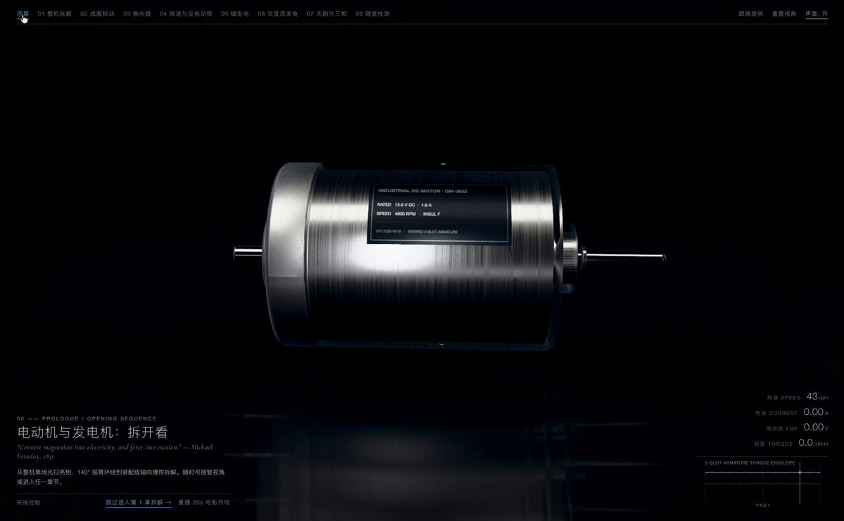
Customize: Electric motor and generator teardown
The prompt comes from a post by WY. Watch the video
Your prompt
The highlighted part at the end is added from your details and dials. Where it disagrees with the prompt, it wins.
# Task: Make a web 3D teaching experiment "Motor and Generator: Take it apart"
Technology stack: Three.js r163+ (ES modules) + native JS/CSS. All models are modeled procedurally. The goal of the picture is "high-end industrial product disassembly film", referring to the explosion shots of Apple product launches, Dyson product cutaway videos, and KeyShot studio renderings.
**Execution order (mandatory)**:
1. Write a brief design (chapter, model list, shot list) and give it to me for confirmation;
2. Use the "shader ball test scene" (see Chapter 3) and take screenshots to confirm the gloss;
3. Set up the camera system and make a 20-second opening shot, export the frame-by-frame screenshots to me to confirm the camera movement;
4. After confirming all the above, complete the implementation.
**Explicitly prohibited**: Neon glow, cyber grid, glass mimic panel, strong bloom, high saturation magnetic induction line, plastic-like metal, crude model made of squares and cylinders, card-style instrument panel, linear interpolation mechanical mirror movement, camera teleportation, lens shake and pause.
---
## Chapter 1 Gloss: Metal must be "as bright as real"
### 1.1 Rendering pipeline (the most common mistakes are here)
- Renderer settings: `outputColorSpace = SRGBColorSpace`, `toneMapping = NeutralToneMapping` (Khronos PBR Neutral, product rendering color is the most accurate; fall back to AgXToneMapping when unavailable), `toneMappingExposure` is adjusted between 1.0–1.3.
- EffectComposer's render target must use `HalfFloatType` (HDR), so that the highlight can exceed 1.0 and Bloom can only capture the true highlight point.
- **The last Pass in the post chain must be OutputPass**, where tone mapping and sRGB conversion are done. Without it, the whole picture would look gray and flat.
- Anti-aliasing: composer render target is turned on `samples: 4`; high-end devices can add SMAA. Pixel ratio upper limit 2.
### 1.2 The metal background color must use true reflectivity (no darkening allowed)
The "dark" part of the metal comes from the black surroundings it reflects, not the base color. The background color is given according to the physical F0 value, and the following are the sRGB values:
| Material | Background color | metalness | roughness | Remarks |
|---|---|---|---|---|
| Polished steel (shaft) | `#c9cbcd` | 1 | 0.08–0.12 | To clearly reflect the shape of the light strip |
| Brushed aluminum / stamped steel shell | `#d6d8da` | 1 | 0.32 | `anisotropy 0.7`, brushed in circumferential direction |
| Sandblasted cast aluminum (end caps) | `#cfd1d3` | 1 | 0.48 | Fine noise roughness map, range 0.4–0.56 |
| Brass commutator | `#f2d9a0` | 1 | 0.22 | `anisotropy 0.6`, along the direction of rotation; brush contact zone roughness 0.1, brighter |
| Enameled copper wire | `#eaa27c` | 1 | 0.28 | `clearcoat 1`, `clearcoatRoughness 0.05`; add varnish to the bottom copper to produce double-layer highlights |
| Silicon steel sheet (with insulating coating) | `#9a9ea3` | 0.85 | 0.4 | A thin dark line on each piece along the axial direction; end stamping edge roughness 0.2 brighter |
| Balls / Bearing Rings | `#d0d2d4` | 1 | 0.06 | Small, sharp highlights |
| Nickel-plated neodymium magnet | `#d8dadc` | 1 | 0.18 | |
| Ferrite magnet | `#3b3d40` | 0 | 0.7 | Non-metal matte; only low saturation marking paint is applied on the pole surface, N `#b5534a`, S `#4f74a8` |
| Mica flakes | `#3a2614` | 0 | 0.55 | |
| Carbon brush | `#2a2a2c` | 0 | 0.85 | |
| Plastic parts | `#1d1f22` | 0 | 0.5 | clearcoat 0.15 |
- `envMapIntensity` is set to 1.2–1.5 for metals and 0.8–1.0 for non-metals.
- The drawing direction is realized with MeshPhysicalMaterial's `anisotropy` + `anisotropyRotation` (or anisotropyMap); the UV of the cylindrical part must be expanded along the circumference, otherwise the drawing direction will be wrong.
### 1.3 Roughness must vary (this is the source of "realism")
Each metal needs a procedurally generated roughness map (Canvas, 1024², anisotropy 8), consisting of three layers:
1. **Main Texture**: Brushed (thousands of thin lines with random grayscale length) or sandblasting (fine noise);
2. **Low-frequency patches**: Use 2-3 large-scale noises to make the roughness fluctuate ±0.06, simulating traces of hand touching and wiping;
3. **Sparse Thin Scratches**: 20–60 short, bright, thin lines per texture, with random lengths and random directions.
In addition: the wear areas such as the commutator plate contact belt and the bearing raceway should be smoother; the corners should be slightly rough.
### 1.4 Bevel (it determines where the highlight falls)
**All sharp edges** must be rounded with a radius of 1–3% of the part size, in at least 3 segments, with smooth transitions from normals. Without chamfers, the edges won’t catch the highlights and the whole part will look like a CG block. Use LatheGeometry for turned parts (rotating shaft, commutator, end cap), and draw chamfers directly on the contour line; use ExtrudeGeometry for extruded parts, with `bevelEnabled` and `bevelSegments ≥ 3`.
### 1.5 Environment and lighting: large area of pure black + a few bright lights
Metal reflects what it reflects, so the **environment must be extremely contrasting**: 90% pure black, 10% very bright, soft-edged light.
- **Environment Map**: Use PMREMGenerator.fromScene to bake a studio with `sigma` set to 0 to retain sharp reflections.
- Room: reverse sphere, color `#050607` (close to pure black).
- Lights: Use a plane with a gradient texture (bright in the center, 20% soft falloff at the edges), multiplied by a high brightness factor with a MeshBasicMaterial. The HDR brightness needs to be enough so that the metal will be bright.
- Large softbox on top: 10×4, color `#f4f1ea`, brightness ×8, position (0, 9, 3);
- Left rear long light strip: 0.8×12, color `#d4e3ff`, brightness ×14, position (-7, 2, -5), placed vertically, pulling out a cold long highlight on the cylindrical piece;
- Thin light strip on the right rear: 0.4×10, color `#fff2e0`, brightness ×12, position (7, 3, -4), giving warm edges to copper and brass;
- Front low-position weak reflector: 6×1.5, color `#ffffff`, brightness ×2, position (0, -1, 8), leaving a light highlight on the downward facing surface;
- The rest of the environment remains black. Black itself is "negative light", and the dark bands on the metal are formed by it, making the dark bands look sharp.
- **RectAreaLight** (real-time, movable, used to generate sliding highlights): initialize RectAreaLightUniformsLib, put 2 blocks:
- A light: 0.3×3, intensity 18, color `#ffffff`, placed vertically on the left rear of the subject;
- B light: 2×0.4, intensity 10, color `#ffe9d0`, placed horizontally on the upper right side of the subject.
- **DirectionalLight main light**: only responsible for projection, intensity 1.2, shadow map 2048, `radius 4`, shadow camera close to the subject.
- **HemisphereLight**: intensity 0.15, sky color `#d7dde6`, ground color `#121110`, only used to hold the dark parts.
- **Highlights must move**:
- During standby, the A light slowly sweeps back and forth across the subject along an arc, with a cycle of about 14 seconds;
- Each time the camera switches, `scene.environmentRotation.y` rotates 15–30% with the camera azimuth angle, allowing the reflection to slide with the lens;
- The opening "Light Sweep Appearance": the main body starts from completely black, a light strip sweeps from left to right, and the metal is lit up in turn, which takes about 2.4 seconds.
### 1.6 Ground
- Use Reflector, the resolution is 1/2 of the canvas, and do 9 sampling blurs in the shader. Ground background color `#0b0c0e`, Reflection Blend 0.22, radially decaying to 0 with distance from the subject.
- Add a soft oval directly below the subject to touch the dark spot.
- Do not put any grid or text on the ground.
### 1.7 Late chain (fixed order)
1. RenderPass (HDR, MSAA).
2. **GTAOPass**: radius is 2–3% of the body diameter, `thickness 0.8`, `distanceExponent 1.5`, `samples 12`; noise reduction parameters `lumaPhi 10`, `depthPhi 2`, `normalPhi 3`, `radius 5`, `rings 2`, `samples 12`; blending strength 0.8.
3. **Contour Pass** (read GTAO’s depth and normal):
- 4 neighbor samples; the depth jump is calculated with the relative value `(z - zn) / -z`, and only the far edge is traced after `smoothstep(0.012, 0.04)`;
- Normal jump multiplied by 0.45;
- Thread color `#07090a`, mechanical body strength 0.2, schematic coil strength in principle mode 0.5.
4. **Bloom**: threshold set to 1.0 (HDR value, only specular highlights and glowing elements exceed it), strength 0.25, radius 0.35. The goal is to have a small, bright "flash point" on the steel ball and polished shaft, not the entire piece to shine.
5. **Color Pass**:
- Light S-curve `mix(c, c*c*(3-2c), 0.14)`;
- The highlights are slightly warm and the shadows are slightly cold, each about ±0.008;
- Vignetting strength 0.45;
- Dark film grain 0.015.
6. BokehPass (only enabled in close-up, see Chapter 2).
7. **OutputPass** (required).
**Adaptive Downgrade**: When the frame rate continues to be lower than 45, the following processing is performed: GTAO and Contours → Reflection down to 1/4 → Bloom → RectAreaLight down to 1 block → Pixel Ratio → Shadows.
---
## Chapter 2: Mirroring: Shooting like a photographer, not two-point interpolation
### 2.1 Camera system (build this first, then create content)
Write a CameraDirector to manage three modes uniformly:
- **Lens Mode (Shot)**: Press the shot list to play the preset shot;
- **Follow mode (Follow)**: The camera tracks a target, such as a selected part or a rotating coil;
- **Free mode (Free)**: User operates with OrbitControls.
Camera status = camera position, gaze point target, focal length fov, roll roll, focus distance focus. The five quantities are interpolated independently.
**Data structure of lens**:
- `path`: the camera path points of the Catmull-Rom spline (at least 3 points, ensuring an arc);
- `target`: gaze point path (can be a fixed point or a spline);
- `fov`: starting and ending values;
- `roll`: starting and ending values;
- `dur`: duration;
- `ease`: ease;
- `focus`: focus target;
- `hold`: the residence time after settling;
- `onSettle`: Event triggered after settling (subtitles, annotations).
**Interpolation rules**:
- **Focus leading, camera following**: The gaze point is eased about 15% faster than the camera position, imitating the photographer who first turns his head and then moves his body.
- ** Use easeInOutQuint for large-scale lens movement, and easeInOutCubic for small-scale movement. Linear interpolation is strictly prohibited. **
- **Speed Continuous**: When the shot is interrupted, it will smoothly transition from the current position and current speed to the new shot (transition with critical damping spring for about 0.4 seconds). It cannot restart from a standstill, let alone skip frames.
- **Roll**: Add an inclination of no more than 1.5° when moving along an arc, and return to normal after reaching it, imitating a rocker arm.
- **Focal Length Breathing**: When the lens is pushed in, the FOV is simultaneously narrowed by 2–4°, and when the lens is pulled in, the FOV is relaxed to increase the sense of depth.
- **Speed limit**: The camera angular speed does not exceed 35°/s, and the translation speed does not exceed 0.8 times the diameter of the subject/s.
- **Settling**: After the camera settles, it pauses for 0.4–0.8 seconds before subtitles and annotations fade in. Subtitles never appear at the same time as camera movements.
**Handheld micro-movement**: During the stay in Shot and Follow modes, extremely light Berlin noise is superimposed on the camera position and gaze point: the amplitude is 0.15–0.25% of the observation distance, the frequency is about 0.15–0.3Hz, and the phases of the two components are different. The nudge will fade out as soon as the user starts the operation. This item is small, but it can make the picture "come alive".
### 2.2 Composition
- Place the main body near the three-point line, leaving negative space for the title in the lower left corner and the data on the right.
- When the sidebar or drawer is open, use `camera.setViewOffset` to pan the screen instead of moving the camera. The position of the subject in the picture is adjusted accordingly, and the perspective remains unchanged.
- Use a slight elevation angle for the protagonist lens: the camera is slightly lower than the center of the subject and looks upward 5–10° to make the subject appear thick and powerful; use a 25–35° overhead view for the explanation lens.
- Each shot must have bright parts, dark parts and highlights at the same time; the reflection of the light strip on the metal must be visible when positioned. Don’t choose an angle that makes the subject look dead.
### 2.3 Lens language (the following shots must be made, and each one must be written clearly in the shot list)
1. **Black point light sweep debut**: A completely black opening, a light strip sweeps across, the outline of the subject is highlighted in turn, and then the camera slowly advances about 15% from a low position. Approximately 5 seconds total, with citation in italics and serif.
2. **Surround display**: Make a half circle around the main body along an arc of about 140°, slightly raise it, and roll at the same time. The reflection of the lamp flows on the housing.
3. **Explosion Disassembly**: While the parts are separated along the axis, the camera is pulled back and raised by about 20°, and the FOV is widened by 4°, ensuring that all parts are within the frame throughout the process. Parts fly out sequentially in assembly order, with a delay of 80–120 milliseconds for each part, with slight deceleration rebound; the screw rotates before exiting.
4. **Tile display (knolling)**: Cut from the explosion state to the orthogonal perspective (FOV reaches 18°, the camera rises directly above). All the parts fly to the ground and are arranged in a neat grid, with thin line markings appearing under each part. This is a very classic shot in product films.
5. **Macro focus transfer**: Push to close-up of commutator and brush, FOV 18–22°, open depth of field. The focus is pulled from the commutator to the carbon brush, which takes about 1.2 seconds, and the background is defocused into a soft spot.
6. **Parallel Sliding**: The laminate stacked against the silicon steel sheet moves laterally, and the lamination line slides across the screen, forming a parallax between the foreground and the background.
7. **Section advancement**: The section plane is slowly advanced from the surface of the casing to the central axis, and the camera moves sideways simultaneously to keep the section facing the lens.
8. **In-situ transition (real machine → principle model)**: The camera does not move, the real parts fade out, and the schematic coil and magnetic pole fade out, both sharing the same corner. The camera then slowly zooms in on the coil.
9. **Follow rotation**: When the coil rotates, the camera follows it at an angular speed of 0.3 times, making the coil appear to rotate slower and easier to read in the picture. Users can turn off following.
### 2.4 User free operation
- OrbitControls: `enableDamping`, `dampingFactor 0.06`, `rotateSpeed 0.55`, enable cursor-centered zoom; limit pitch angle and zoom range.
- Double-click a part: Calculate the appropriate distance based on its surrounding sphere, use a 1.2-second arc to push the camera over and align it, and the background part will darken.
- The camera does not rebound after letting go; after 8 seconds of inactivity, lens micro-motion and highlight sweep will fade in again.
- Each chapter provides a "reset perspective", which allows you to go through an arc and return to the default lens of the chapter. Teleportation is not allowed.
---
## Chapter 3 Acceptance Method (both luster and mirror movement must speak for themselves with evidence)
### 3.1 Shader test scene (must be completed before modeling and let me confirm)
- Under the final studio lighting, make a chamfered test piece for each material in the table above and arrange them in a row: one each for a sphere, a cylinder with chamfers, and a box with chamfers.
- Take 3 pictures: front, 45°, low camera angle.
- Check items one by one:
- The shape of the light strip can be clearly seen on the steel balls and polished shaft;
- The highlight of a brushed piece is an elongated band rather than a dot;
- The copper wire has a double layer of high gloss (varnish layer and copper layer);
- Each metal piece has both a nearly pure black dark band and a very bright highlight band;
-Nothing looks like gray plastic.
If it's not up to standard, adjust the lighting and environment first, then the material, and finally the exposure.
### 3.2 Mirror operation acceptance
- Export frame-by-frame screenshots of the opening 20 seconds using a virtual clock at a fixed 60fps step (one every 6 frames to create a contact sheet).
- Simultaneously record the camera speed and angular speed of each frame into a graph. The curve must be smooth and continuous: no spikes, no jumping to zero, no exceeding the speed limit.
- Interruption test: trigger another lens in the middle of the camera movement to check whether the speed curve is continuous.
### 3.3 Self-examination of screenshots of the finished film
After each chapter is completed, check it according to the standards of 3.1. Also check: whether there are contact shadows between parts; whether there are reflections on the ground; whether magnetic lines of induction are restrained; whether there are card panels or neon lights in the picture.
---
## Chapter 4 Model Details (Engineering Level)
- The enameled wire is modeled turn by turn, and a real coil cross-section is wound along the slot; the end must have a bulge, a tie and a lead wire, and the lead wire is welded to the hook of the commutator piece.
- Rotor core: real groove shape, optional number of grooves (3 / 5 / 12 grooves), with inclined grooves; lamination lines visible.
- Commutator: real number of pieces, with mica seams between the pieces; the brush is installed in the brush holder, and there is a compression spring behind it.
- Shell: mounting holes, screws, etched nameplate (model, rated voltage, speed), ventilation holes, solder joints.
- Bearing: ball bearing with cage; circlip and keyway are added at the end of the rotating shaft.
- Bevel all sharp edges (see 1.4). All objects are modeled with reasonable real-life sizes (small motor diameter is about 30–40mm, unified in millimeters, or scaled as a whole), otherwise the parameters of the lights and AO will be invalid.
## Chapter 5 Scientific Visualization (Restrained Overlay)
- **Magnetic induction line**: extremely thin pipeline, color `#9fc3e6`, transparency 0.5, with a slow-flowing dotted line texture along the N→S direction, which must pass through the magnetic steel and the iron core. The stronger the magnetic field, the denser the lines and the faster they flow. Magnetic field lines do not participate in Bloom.
- **Current**: Warm-colored small light spots `#ffcf8a` flowing along the wire. The density and brightness of the light spots are proportional to the size of the current; the direction of the light spots must be visibly flipped at the moment of reversal.
- **Force**: White matte solid arrow, the length is proportional to the force.
- **Brush Sparks**: Tiny warm white particles, the higher the speed, the more obvious they are, but be restrained.
- **Cutting**: Use clippingPlanes to cut and stencil to block. Sections are colored according to material and given a very light 45° hatch.
- **Focus**: When a part is selected, the remaining parts are reduced to 15% brightness and desaturated.
- **High Speed Rotation**: At high speed, angular motion blur is added to the commutator segments and notches.
## Chapter 6 Interface (Editorial Documentary HUD)
- Page background color `#040507`; main text color `#f2f4f7`, main text `.78`, secondary `.5`, weakest `.3`, thin line `rgba(220,228,240,.16)`; the only accent color is ice blue `#6fb2e6`.
- Font: Sans serif `"Helvetica Neue", "Noto Sans SC", "PingFang SC"`, title weight 200–300; use italic serif `"Cormorant Garamond"` for embellishment.
- An enlarged and thin font title in the lower left corner, a kicker with widened word spacing above it (e.g. `04 - DC MOTOR / TEARDOWN`), and a line of italic citations below (e.g. "Faraday, 1831").
- Place a right-aligned digital stack on the right side: speed, current, electromotive force, torque.
- Waveform diagram: SVG thin line, no background frame, with a vertical line that moves synchronously with the rotor angle; the neutral plane and reversal point are marked with dotted lines.
- The control is made into "text link + 1px slider". Parts are marked with leader lines, and labels follow the projected position and prevent overlap. Tips for making movie subtitles at the bottom. Pad radial gradient scrim behind text.
- No card, no frosted glass, no shadows. In the vertical screen of the mobile phone, the 3D area accounts for more than 60% of the screen, and the explanations are stored in the bottom drawer.
- Optional: Use WebAudio to synthesize motor sound (the fundamental frequency changes with the speed, superimposing commutation harmonics and brush noise), muted by default.
## Chapter 7 Teaching Content
Corresponding to "Electromotor, Magnetism and Electricity" in junior high school and "Electromagnetic Induction, Alternating Current" in high school, the interface does not indicate the academic level. Core concept: dismantle the real machine to see the structure, the principle model to see the essence, and switch between the two in situ.
1. **Complete machine appearance and disassembly**: Understand the casing, stator magnets, rotor core, windings, commutator, brushes, bearings, and rotating shafts.
2. **Why does the energized coil rotate**: Left-hand rule, the effective side is stressed, and the torque changes with the rotation angle; the coil stops at the equilibrium position, which leads to the commutator.
3. **Commutator**: The moment when the slow discharge current reverses. The number of commutation plates is adjustable (2 / 3 / 5 / 12), and the torque ripple curve becomes smooth accordingly. The number of slots and the number of plates of the real machine change simultaneously.
4. **Factors affecting speed and steering**: voltage, magnetic field, number of turns, direction reversal, and back electromotive force (the current light spot becomes thinner when the speed increases).
5. **Magnetic electricity**: right-hand rule; neutral plane; e = E_m·sinωt, E_m = NBSω. There are four sliders for rotation speed, magnetic field, number of turns, and area, each of which changes the waveform and image at the same time.
6. **AC and DC generator**: Slip rings and commutators can be interchanged, and the waveforms of sinusoidal AC and pulsating DC can be compared in real time; then disassemble a real alternator.
7. **Expansion**: Brushless motor, three-phase generator (the three sets of coils are 120° apart).
8. **On-site testing**: Click in 3D, judge the direction, select the waveform, and use animation playback to explain after judging the score.
**Principle**: Every slider and switch must produce a visible change in the 3D image.
**Physical requirements**: Use the simplified DC motor equation U = E + IR, E = kω, T = kI, and take the parameters as real small motors (3–12V, thousands of rpm). The corners are strictly synchronized with the waveform. Write unit tests for the following relationships: the neutral plane electromotive force is zero; E_m is proportional to N, B, S, and ω; the direction of the torque remains unchanged before and after commutation.For best results, run it with Gemini 4 Carbon.